Serial Input Paralel Output Sipo
Dec 2, 1990 - The 74HC/HCT4015 are dual edge-triggered 4-bit static shift registers (serial-to-parallel converters). Each shift register has a serial data input. How to design a 4-bit Serial In Parallel Out shift register (SIPO)? Then we know that we have a serial output so let’s connect the output of the last flip-flop to the output pin. The first flip-flop also does not need a serial input because there is no preceding flip-flop. Parallel in, parallel out, serial input.

What is Shift Register: Shift Registers are sequential logic circuits, capable of storage and transfer of data. Download game chess gratis untuk hp. They are made up of Flip Flops which are connected in such a way that the output of one flip flop could serve as the input of the other flip-flop, depending on the type of shift registers being created. Shift registers are basically a type of register which have the ability to transfer (“shift”) data. Registers are generically storage devices which are created by connecting a specific number of flip flops together in series and the amount of data (number of bits) which can be stored by the register is always directly proportional to the number of flip flops, as each flip flop is capable of storing only one bit at a time. When the flip-flops in a register are connected in such a way that the output of one flip flop, becomes the input of the other, a shift register is created. Flip Flops are devices with an operation similar to that of a latch.
It can be referred to as a which can move between two states (0 or 1) and is capable of storing data in bits. New data is read into a flip flop with each clock cycle and the previous data sent at the output. This however depends on the kind of flip flop, as the Input, Output, and clock cycle relationship between flip flops vary. There are different kinds of flip flops, but the most commonly used in the creation of shift registers are the. For the operation of the D flip flops which makes them so desirable for shift registers, Whenever there is a change on the clock of a D flip flop (either rising or falling edge, depending on the specifications of the flip flop). The data at the output “Q” becomes the same data as the one at the input “D”.
The Output “Q” of the flip flop will stay at that value until the next clock cycle, where it will then change again to the value(High or low, 1 or 0) at the input. Types of Shift Registers Shift registers are categorized into types majorly by their mode of operation, either serial or parallel. There are six (6) basic types of shift registers which are listed below although some of them can be further divided based on direction of data flow either shift right or shift left. Serial in – Serial out Shift Register (SISO) 2.
Counter strike 1.6 game (pc) highly compressed only 64 mb. Download counter strike 1.6 full version highly compressed and enjoy game. Counter Strike 1.6 Free Download Full Version PC Game Cracked in Direct Link and Torrent, Counter Strike 1.6 Highly Compressed Free Download Full Version. Counter Strike 1.6 is a action video game. Counter Strike 1.6 is a action video game. Counter strike 1.6 download for pc if you are searching for downloading counter strike in compressed version then you are reached at right place because here i will give you the download link of counter strike 1.6 for downloading this game. Download counter strike 1 6 pc highly compressed games pc.
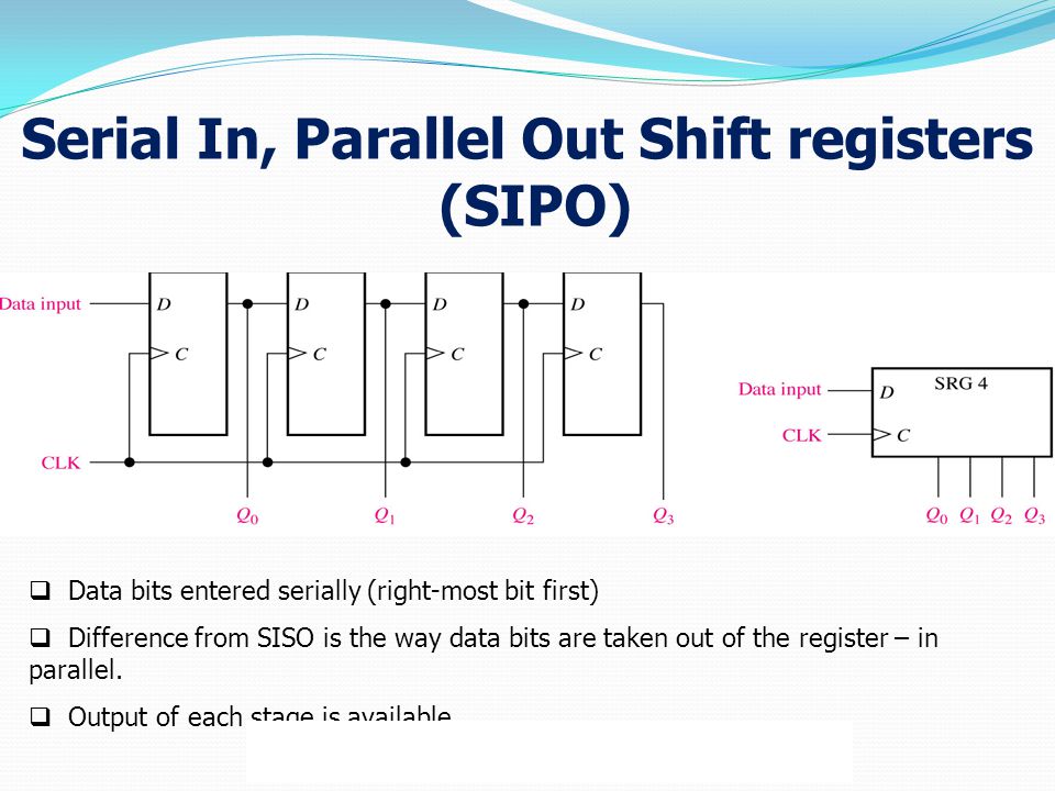
Serial In – Parallel out shift Register (SIPO) 3. Parallel in – Parallel out Shift Register (PIPO) 4. Parallel in – Serial out Shift Register (PISO) 5. Bidirectional Shift Registers 6. Serial in - Serial out Shift Registers Serial in – Serial out shift registers are shift registers that streams in data serially (one bit per clock cycle) and streams out data too in the same way, one after the other.
A simple serial in – serial Out 4-bit shift register is shown above, the register consists of 4 flip flops and the breakdown of how it works is explained below; On startup, the shift register is first cleared, forcing the outputs of all flip flops to zero, the input data is then applied to the input serially, one bit at a time. There are two basic ways of shifting data out through a shift register; • Non-destructive Readout • Destructive Readout • Non-Destructive Readout Non - Destructive readout based, shift registers always have a read/write mode of operation with an extra line added to allow the switch between the read and write operational modes. When the device is in the “write” operational mode, the shift register shifts each data out one bit at a time behaving exactly like the destructive readout version and data is thus lost, but when the operational mode is switched to “read”, data which are shifted out at the input goes back into the system and serve as input to the shift register. This helps ensure that the data stays longer (as long as it stays in read mode) • Destructive Readout For destructive readouts, the data is completely lost as the flip flop just shifts the information through. Assuming for the 4-bit shift register above, we want to send the word “1101”. After clearing the shift register, the output of all the flip flops becomes 0, so during the first clock cycle as we apply this data (1101) serially, the outputs of the flip flops look like the table below. First clock cycle: FF0 FF1 FF2 FF3 1 0 0 0 Second clock cycle: FF0 FF1 FF2 FF3 0 1 0 0 Third Clock Cycle: FF0 FF1 FF2 FF3 1 0 1 0 Fourth Clock Cycle: FF0 FF1 FF2 FF3 1 1 0 1 2.